Multiple socket-outlets on medical devices
Naturally, multiple socket-outlets are needed for medical devices in daily practice as well. However, a lot of people are unaware of the regulatory consequences of using multiple socket-outlets.
This article will give you the necessary overview:
- What risks does using multiple socket-outlets lead to?
- How can you can identify, analyze and avoid these risks?
- Which regulatory requirements you have to comply with when using multiple socket-outlets?
1. Using multiple socket-outlets
Operators, e.g. hospitals, use multiple socket-outlets to:
- extend power supply cords that are too short
- compensate for a lack of wall socket-outlets
- be able to disconnect several devices from the power supply at the same time and then reconnect them again at another location for patient transport
- combine medical devices (strictly speaking medical electrical equipment (ME equipment) and non-ME equipment to create an (ME) system, for example on a trolley
2. Definition and examples
IEC 60601-1 defines the term multiple socket-outlet as follows:
Definition: Multiple socket-outlet
“one or more socket-outlets intended to be connected to, or integral with, flexible cables or cords or ME EQUIPMENT for SUPPLY MAINS or equivalent voltage”
Source: IEC 60601-1
Multiple socket-outlets are often used on equipment trolleys in hospitals, e.g., for endoscopies, rounds or ultrasound equipment. In these cases, you come across multiple socket-outlets:
- as an integral part of equipment or connected to (ME) equipment via flexible cables
- as a stand-alone MSO
- as an individual socket-outlet on ME equipment A fixed installation in a wall, in contrast, is not a multiple socket-outlet as defined by the standard.
3. Risks and hazards from multiple socket-outlets
Overview
IEC 60601-1 has good reasons to specifically regulate the use of multiple socket-outlets:
A common protective earth conductor: A multiple socket-outlet has one common protective earth conductor (PE conductor) for all connected devices. In other words, if the protective earthing fails, it fails for all the devices.
- Failure of all devices: If the multiple socket-outlet or, to be more precise, a mains conductor in the multiple socket-outlet malfunctions, all the connected devices will cut out.
- Too high a current: The multiple socket-outlet must be able to carry the total current or total power of all the connected devices.
- Cable breaks: The probability of a cable breaking is higher than with fixed sockets due to the flexible and not permanently installed connection cable.
- Multiple socket-outlet cascading: Users like to connect additional multiple socket-outlets to a multiple socket-outlet, which multiplies the risks.
- Tripping hazard: Multiple socket-outlets are dangerous tripping hazards.
- Damage: Multiple socket-outlets are typically placed on the floor. Therefore, they can easily be mechanically damaged or exposed to liquids.
- Effect on ME equipment: Users often connect both ME equipment and non-ME equipment to multiple socket-outlets. In the event of a fault, the non-ME devices have a (negative) effect on the ME devices via the multiple socket-outlet.
- Paralyzing of entire fuse sections: The earth leakage currents add up across the multiple socket-outlets and can also trigger a residual current circuit breaker, which then “paralyzes” entire socket-outlet groups or rooms.
- Higher touch current: The multiple socket-outlet (contact and its power supply cord) increases the protective earth resistance, which can in turn lead to an increased touch current. The accumulation of the earth leakage current would also lead to an excessive touch current in the metallic parts connected to the protective earth conductor if the protective earthing in the multiple socket-outlet's power supply cord cable has been interrupted.
Examples
Touch current
In this example, the total impedance of the protective earthing system is calculated from the sum of the impedances of the building protective earth, the multiple socket-outlet, the power supply cord and the device-internal protective earth system - 0.5 ? in the example.
Even if each part meets the requirements individually, a short circuit (earth contact) in the ME equipment would lead to an excessively high touch voltage and thus to a high touch current. In the worst case, the impedance of the protective earth system can limit the short-circuit current to such an extent then the fuse is not tripped.
These two cases must be avoided under all circumstances.
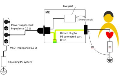
Fig. 1: Risk of an electrical hazard in the event of a short circuit (earth contact) and increased PE resistance. The multiple socket-outlet contributes to the overall impedance.
Earth leakage current
If several ME devices and non-ME devices are connected via one multiple socket-outlet, the earth leakage currents (IEL1, IEL2, IEL3) of all devices in the protective earth system of the multiple socket are added together. In the event of a single fault condition in the multiple socket-outlet, there may be an increased touch current It. In addition, an interruption in the mains conductor of the multiple socket-outlet can lead to all the ME equipment cutting out.
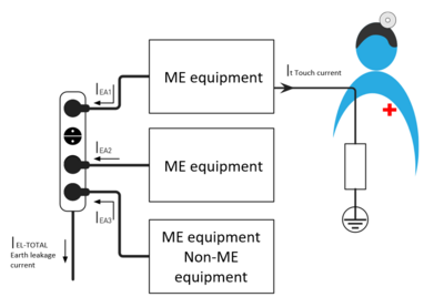
Fig. 2: The earth leakage current I-total must not exceed 5 mA in the normal state or 10 mA in a single fault condition.
Hazards
All in all, the following hazards (among others) are generated:
- Thermal hazard from overloads or poor contacts.
- Electrical hazards from an increase in the touch current when the PE is interrupted or when the PE resistance increases
- Functional hazard from potential interruption of the power supply for connected ME equipment.
However, we should also mention a positive side effect: A multiple socket-outlet acts a potential equalizer for the connected devices.
4. Regulatory requirements
Legal requirements
In the general safety and performance requirements, the EU directives (e.g., MDD) and EU regulations (e.g., MDR) explicitly require electrical, thermal and functional safety, i.e., the protection of patients and users from the aforementioned hazards.
National laws make these requirements their own and add to them, for example with national regulations such as the German MPBetreibV [Medical Devices Operator Ordinance].
Harmonized standards
In order to demonstrate compliance with these requirements, manufacturers should (must) comply with the relevant (harmonized) standards such as IEC 60601-1 and IEC 60884-1 (“Plugs and socket-outlets for household and similar purposes - Part 1: General requirements”).
Because multiple socket-outlets as described above can have a significant effect on the safety of an ME system, the standard also explicitly establishes requirements for multiple socket-outlets and for devices with integrated multiple socket-outlets.
It stipulates that manufacturers (including operators) must assess components for their suitability for the operating conditions. This includes aspects such as:
- Cable cross-sections, particularly the protective earth conductor
- Contact force
- Cord anchorage
- Mechanical strength of the enclosure
- Marking (safety signs, permissible devices or maximum output in VA)
- Access with tools
The standards specifically require:
- Creepage distances and air clearances for MOOP (Means Of Operator Protection) must be complied with.
- Impedance of the protective earth conductor is < 200 m?.
- MSO must be protection class I.
- The connection and securing of cables must meet the design requirements established in 8.11.4.
- The cable cross-sections must comply with Table 17.
- The design of the cord anchorage must comply with 8.11.3.5 and Table 18.
- The multiple socket-outlet must have a cord guard as per 8.11.3.6.
Section 16.9.2.1 of the standard provides a summary of the most important requirements regarding the use of MSOs in ME systems.
N.B!
Standard multiple socket-outlets from a hardware store are therefore not suitable for use in a ME system or in rooms used for medical purposes.
What is permitted and what isn’t
The following, for example, are not permitted:
- Extending or enlarging a multiple socket-outlet with a second multiple socket-outlet
- Plugging in a European two-pin mains plug (no PE)
- Placing the multiple socket-outlet on the ground
- Connecting devices other than those permitted, unless otherwise specified
On the other hand, it is permissible for the impedance of the protective earth to exceed the specified values, if the touch current and the patient leakage current are not exceeded in a single fault condition.
Responsibilities for multiple socket-outlets
Manufacturers who use a multiple socket-outlet in an ME system or ME equipment are responsible for it. Operators who (mostly unknowingly) build an ME system must also accept this responsibility as soon as equipment is connected via an MSO. An organization then automatically becomes the manufacturer, assumes responsibility and must, therefore, comply with the requirements of the standard.
5. Possible consequences for the system design
Only multiple socket-outlets permitted by the manufacturer
For ME systems marketed by the manufacturer, only devices intended for the ME system may be connected to multiple socket-outlets. A multiple socket-outlet must be clearly marked to show the devices that may be connected according to the intended purpose.
Instructions for use
The manufacturer must describe how to use the multiple outlet-socket in the instructions for use and give a warning stating that no additional MSOs may be connected and that the MSO must not be placed on the floor. Incidentally, the instructions for use are part of the ME system.
If a non-ME device is part of an ME system for which the manufacturer has provided an isolating transformer, the instructions for use must inform the user that the non-ME device must be plugged into another socket-outlet.
Covers
The manufacturer must cover unused open socket-outlets on an MSO in such a way that the covers can only be removed with a tool.
The manufacturer must protect the socket against unintentional unplugging.
Protective measures
Various protective measures are recommended, depending on the specific application.
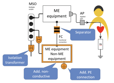
Fig. 3: Protective measures minimize the risks associated with equipment connected via multiple socket-outlets.
6. Tests
How to test?
Testing is done:
- in the form of an inspection, e.g., of the design specifications and layout
- by measuring the leakage currents in the ME system
- by measuring the PE impedance
- in the form of a measurement of the protective conductor’s current-carrying capacity
Who does the testing?
If the manufacturer markets the ME system as a single item, the manufacturer tests it together with the testing laboratory.
If, on the other hand, the operator builds the ME system, the operator is also responsible for testing. This also applies if the operator adds to a manufacturer’s ME system.
What documentation is expected?
The manufacturer and/or operator should be able to provide the following documentation following these tests:
- for ME systems, the instructions for use as support documentation for the multiple socket-outlet
- if applicable, drawings
- test certificates for purchased components
- test documentation (test plan, test results, e.g., leakage currents)
7. FAQ
Isolating transformer
When do I need an isolating transformer? Where can it be installed?
An isolating transformer is in fact always required if non-ME devices are involved. Table I.1 of the standard gives an overview with various set-ups and recommendations for possible measures.
What alternatives are there to the isolating transformer?
One alternative is, for example, using a second protective earth conductor in a non-ME device. This means that the single fault safety is ensured if the primary protective earth conductor is interrupted.
Tests
What leakage currents have be complied out?
In the patient environment: TOUCH CURRENT 500 ?A
Which tests or certifications do I need? Are accredited laboratories necessary?
No
What components have to be used? Do they have to be certified?
It is always helpful to use already tested components (transformers, cables, plugs, PCs, insulations, etc.). If this is not possible, the requirements of the standard must be met.
What does the operator have to do? How does this relate to the safety engineering control?
The operator must comply with the operator ordinance that requires a metrological control and a safety engineering control to be performed at least once per year for certain medical devices. This also applies to installations and systems, such as ME systems, created by the operator themselves and that they operate.
The protective earthing musted be tested by measurement and inspection and the leakage currents must be checked.
Definitions
Is a multiple socket-outlet a functional connection?
Definition from the standard: Connection, electrical or otherwise, including those intended to transfer signals, data, power or substances.
A functional connection is not necessarily electrical in nature. For example, a data cable is a functional connection. The manufacturer must take the effect of the shield into account. Excess leakage currents can flow via the shield. See figure 3 below.
What is the difference between a system and a procedure pack?
ME system is defined in the standard. If the manufacturer markets a system as a single item, then it may be a procedure pack. However, this is not the same as what the MDR means by the term procedure pack. The standard is about safety and performance.
A procedure pack is defined in Article 12 of the MDD and has a legally defined meaning with regard to conformity with the essential requirements and the operator's responsibilities.
The term is not defined. Helpful definitions:
- System as a functionally assembled group of devices with a clearly defined medical purpose. (group of products)
- Procedure pack is an application-specific assembled group of devices.
- The term procedure pack excludes a combination with drugs. That would be a combination product.
What is considered in-house production?
If the operator extends the system by connecting devices other than those permitted by the manufacturer or by connecting several ME devices via a multiple socket-outlet for one of the purposes specified in #1.

Back To Top
Privacy settings
We use cookies on our website. Some of them are essential, while others help us improve this website and your experience.